What is Lightning?
Lightning is a sudden electrostatic discharge created by the friction between particles in the atmosphere. The discharge releases a massive amount of energy, visible as a flash of light (lightning) and heard as a thunderous sound.
Key Characteristics of Lightning
- Flash of Light :The intense light emitted from the discharge.
- Thunder :The sound produced by the rapid expansion of air due to the intense heat of the lightning bolt.
- Heat :The temperature of a lightning bolt can reach up to 30,000 Kelvin (53,540°F), which is five times hotter than the surface of the sun.

Lightning Discharge Process
Lightning is a powerful natural phenomenon that can cause significant damage to buildings, infrastructure, and human life.
- 1 Charge Buildup Within clouds, water droplets and ice particles move around due to turbulent air currents, which generates positive and negative charges.
- 2 Potential Difference The buildup of charges creates a strong potential difference between the regions of the cloud or between the cloud and the Earth’s surface.
- 3 Discharge When the potential difference becomes large enough to overcome the air’s resistance, the lightning strike occurs, discharging the energy.
Types of Lightning
Lightning can occur in various forms, depending on where the discharge takes place.
Cloud-to-Ground (CG) Lightning
- The CG lightning is the most dangerous type of lightning.
- It occurs when a lightning bolt travels from a cloud to the Earth’s surface.
- This form of lightning can cause wildfires, power outages, and damage to buildings.
Cloud-to-Cloud (CC) Lightning
- CC lightning occurs between different clouds.
- This type is more commonly observed in thunderstorms, though it is less dangerous to the ground than CG lightning.
Intra-Cloud (IC) Lightning
- A lightning discharge that occurs within a single cloud.
- This is the most frequent type of lightning, occurring between different regions of a cloud.
- Typically, it is less visible from the ground but can still cause turbulence and contribute to the storm’s severity.
Ground-to-Cloud (GC) Lightning
- A relatively rare phenomenon where lightning moves from the Earth’s surface up to the cloud.
- Usually occurs in tall structures like skyscrapers or communication towers.
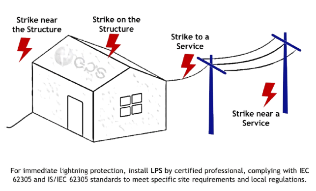
Common Sources of Damages
Lightning damage can be caused by both direct and indirect sources. Direct strikes cause severe, immediate damage to the object or structure struck, while indirect strikes cause damage through electrical surges, ground currents, or side flashes. Proper protection systems are essential to mitigate both types of damage.
| Sources | Damages | Losses | Risks |
|---|---|---|---|
| S1: Flashes to the structure | D1: Injury to living beings | L1: Loss of human life | R1: Risk to human life |
| S2: Flashes near the structure | D2: Physical damage | L2: Loss of service to public | R2: Risk to service to public |
| S3: Flashes to the lines | D3: Failure of internal systems | L3: Loss of cultural heritage | R3: Risk to cultural heritage |
| S4: Flashes near the lines | - | L4: Loss of economic value | R4: Risk to economic values |
| Common Sources of Damages | |
|---|---|
| Sources | S1: Flashes to the structure |
| Damages | D1: Injury to living beings |
| Losses | L1: Loss of human life |
| Risks | R1: Risk to human life |
| Sources | S2: Flashes near the structure |
| Damages | D2: Physical damage |
| Losses | L2: Loss of service to public |
| Risks | R2: Risk to service to public |
| Sources | S3: Flashes to the lines |
| Damages | D3: Failure of internal systems |
| Losses | L3: Loss of cultural heritage |
| Risks | R3: Risk to cultural heritage |
| Sources | S4: Flashes near the lines |
| Damages | - |
| Losses | L4: Loss of economic value |
| Risks | R4: Risk to economic values |
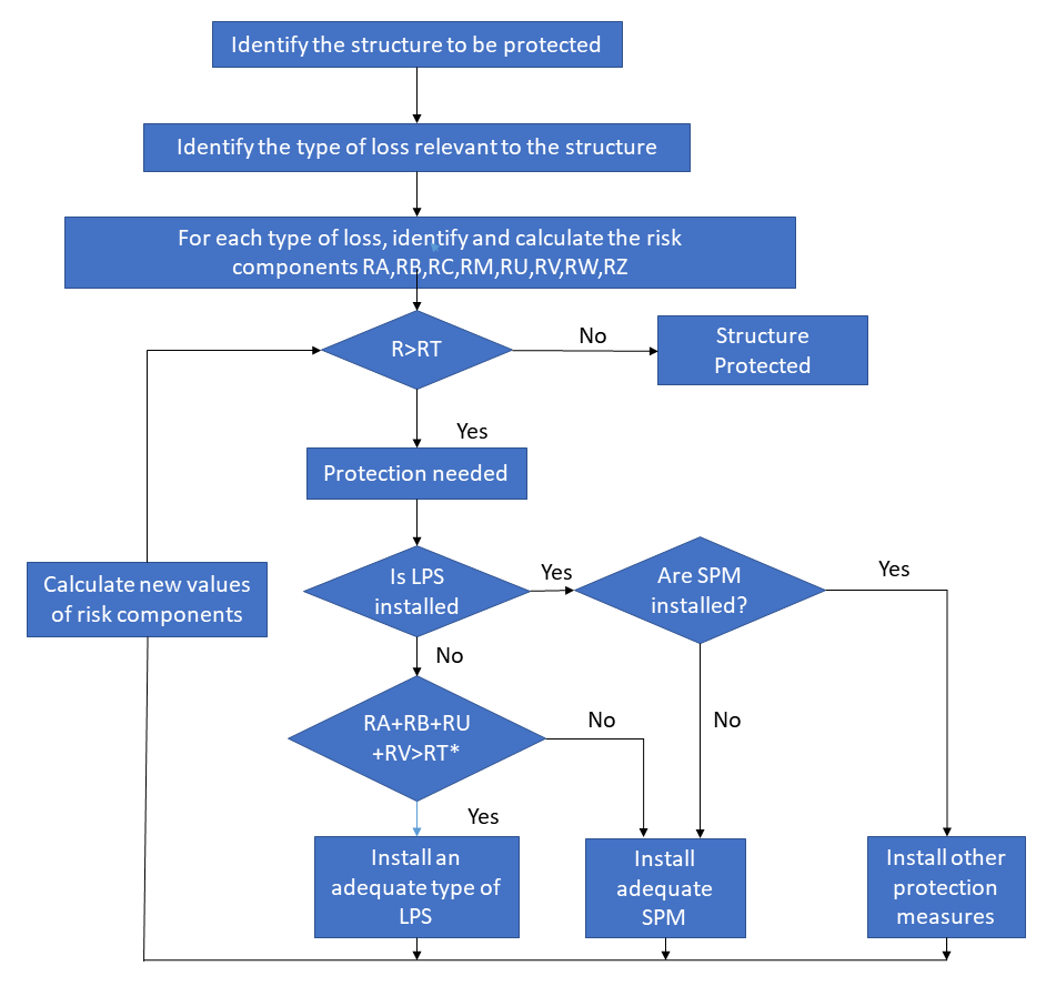
Risk components
Risk components for different types of damage and source of damage
| Damage | Source of damage | |||
|---|---|---|---|---|
| S1 Lightning flash to a structure |
S2 Lightning flash near a structure |
S3 Lightning flash to an incoming line |
S4 Lightning flash near a line |
|
| D1 Injury to living beings by electric shock |
RA = ND × PA × LA | RU = (NL + NDJ) × PU × LU | ||
| D2 Physical damage |
RB = ND × PB × LB | RV = (NL + NDJ) × PV × LV | ||
| D3 Failure of electrical and electronic systems |
RC = ND × PC × LC | RM = NM × PM × LM | RW = (NL + NDJ) × PW × LW | RZ = Nl × PZ × LZ |
| Source of damage | |
|---|---|
| Damage | S1 Lightning flash to a structure |
| D1 Injury to living beings by electric shock | RA = ND × PA × LA |
| D2 Physical damage | RB = ND × PB × LB |
| D3 Failure of electrical and electronic systems | RC = ND × PC × LC |
| Damage | S2 Lightning flash near a structure |
| D1 Injury to living beings by electric shock | |
| D2 Physical damage | |
| D3 Failure of electrical and electronic systems | RM = NM × PM × LM |
| Damage | S3 Lightning flash to an incoming line |
| D1 Injury to living beings by electric shock | RU = (NL + NDJ) × PU × LU |
| D2 Physical damage | RV = (NL + NDJ) × PV × LV |
| D3 Failure of electrical and electronic systems | RW = (NL+ NDJ) × PW × LW |
| Damage | |
| D1 Injury to living beings by electric shock | S4 Lightning flash near a line |
| D2 Physical damage | |
| D3 Failure of electrical and electronic systems | RZ = Nl × PZ × LZ |
Risk Analysis
| Lightning Myths & Facts | |
|---|---|
| Myth | Fact |
| Lightning never strikes the same place twice | Lightning can strike the same place multiple times, especially tall structures like skyscrapers or towers. The Empire State Building is struck by lightning 20-25 times a year. |
| You’re at risk from lightning if you’re inside a car. | A car is a safe place during a lightning storm because its metal frame acts as a Faraday cage, directing the lightning strike around the occupants. Avoid touching metal parts inside the car. |
| Lightning never strikes in clear skies. | Lightning can strike in clear skies, known as a "bolt from the blue." Lightning can travel miles from the storm, hitting areas with no clouds. |
| Lightning only happens during thunderstorms. | Lightning can also occur in other events like volcanic eruptions, forest fires, and sandstorms, where electrical charges can build up. |
| Lightning can’t strike through concrete. | Concrete doesn’t always protect you. If a lightning strike hits a building, its electrical energy can travel through wiring or plumbing. Proper lightning protection is still necessary. |
| Lightning always strikes the tallest object. | Lightning doesn’t always strike the tallest object. It can be attracted to conductive materials, so nearby objects like trees and poles can be hit even if they aren’t the tallest. |
| People who are struck by lightning are always killed. | About 90% of people struck by lightning survive, though they may suffer injuries such as burns or neurological damage. |
| Rubber tires protect you from lightning while driving. | Rubber tires don’t protect you from lightning. A car is safe because its metal frame channels the lightning to the ground, not because of the tires. |
| Lightning can’t strike the same place more than once. | Lightning can strike the same location multiple times, especially in tall, isolated structures like trees or towers. |
| You’re safe from lightning if you’re under a tree. | Being under a tree during a lightning storm is dangerous. Lightning is attracted to tall objects, so a tree can be a lightning rod, putting you at risk of injury or death. |
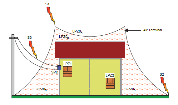
Lightning Protection Zones
Threat is due to- Direct lightning flash- Full lightning electromagnetic field. The internal systems may be subjected to full or partial lightning surge current
LPZ OB is protected from direct lightning strikes and the threat is due to full electromagnetic field. The internal systems may be subjected to partial lightning surge current.
Surge current is limited by current sharing and by isolating interfaces and/or SPDs at the boundary.
Surge current may be further limited by current sharing and by isolating interfaces and/or additional SPDs at the boundary.
Standards for Lightning Protection System
The design, installation, and maintenance of (LPS are governed by various international standards to ensure safety and reliability. These standards provide guidelines for the proper installation of LPS, material selection, and testing.
| Major International Standards | |
|---|---|
| IEC 62305 (International Electrotechnical Commission) |
|
| NFPA 780 (National Fire Protection Association) |
|
| BS EN 62305 (British Standard for Lightning Protection) |
|
| UL 96A (Underwriters Laboratories) | A standard for LPS that focuses on the design and installation of components such as lightning rods, down conductors, and grounding systems in the United States. |
| NF C 17-102 | (French Standard for ESE LPS) |
| BS EN 62305 | (British Standard for lightning protection) |
Key Guidelines and Requirements

Risk Assessment
Determine the level of risk of a lightning strike to a building, based on factors like location, structure height, and nearby hazards.

Design Criteria
The system should be designed to handle the maximum expected lightning current.

Grounding Resistance
The grounding system should have a resistance of no more than 10 ohms, depending on soil conditions.

Regular Maintenance
LPS must be inspected regularly to ensure all components are functioning correctly and that there is no corrosion or wear.
Types of LPS
There are many types of LPS, each designed to protect buildings, structures, and equipment from the damaging effects of lightning strikes. The types of LPS vary in terms of technology and installation methods, with each offering different levels of protection.
1.Conventional LPS (Franklin System)
This is the traditional form of lightning protection. It relies on a lightning rod (also called an air terminal) that is installed at the highest point of a building or structure. The traditional lightning rods rely on a downward lightning strike.
Key Components of Conventional LPS
-
1.Air Terminals (Lightning Rods)
Metal rods are placed at the highest points of the structure to intercept lightning strikes
-
2.Down Conductors
Copper or aluminum cables carry the lightning strike safely from the air terminal to the ground.
-
3.Grounding System
A network of electrodes buried in the ground to dissipate the lightning energy into the ground.
-
4.Bonding and Earthing
Ensures that all metallic parts of the structure are connected to the LPS to prevent electrical surges.
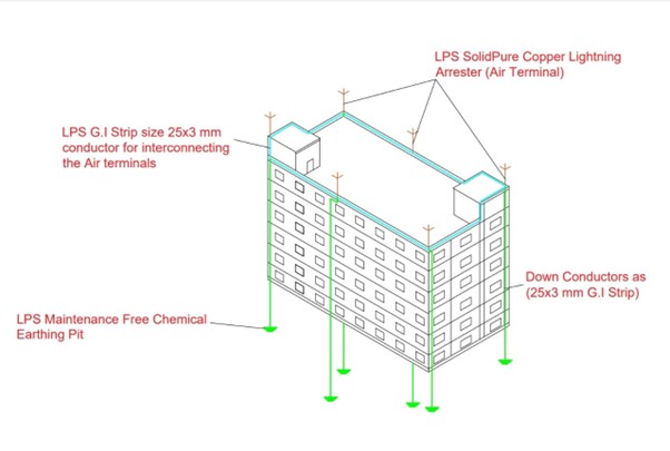
Working Principle
The lightning rod attracts the lightning strike, and the down conductors carry the electrical charge safely into the ground, where it is harmlessly dispersed.
2.Early Streamer Emission (ESE) LPS
An ESE LPS (Early Streamer Emission Lightning Protection System) is an advanced type of LPS designed to provide better protection against lightning strikes, particularly in buildings and structures. The ESE LPS is based on technology that aims to emit an early streamer to trigger a lightning strike in a controlled way, providing an enhanced level of protection.
How ESE LPS Works
The principle behind the ESE LPS is to attract lightning strikes earlier than conventional lightning rods. Here’s how it works:
1.Early Streamer Emission
- The ESE system uses an ESE air terminal (also called lightning rod), designed to emit an early streamer in advance of the lightning strike. The “streamer” is a small electrical discharge that grows toward the storm cloud.
2.Triggering a Lightning Strike
- This early emission helps in attracting the lightning to the air terminal, creating a safe path for the discharge to flow through the lightning protection system and into the ground. The idea is that by initiating the strike earlier, the system reduces the risk of a lightning strike hitting unintended areas of the structure.
3.Controlled Discharge
- The system is designed to channel the lightning strike safely into the grounding system, preventing damage to the structure and electrical systems.
Key Components of ESE LPS
-
1.ESE Air Terminal
The device that emits the early streamer to attract the lightning.
-
2.Down Conductors
Cables that carry the lightning energy from the air terminal to the ground.
-
3.Grounding System
A set of electrodes buried in the earth to safely dissipate the electrical charge into the ground.
Benefits of ESE LPS
-
1.Early Lightning Strike Attraction
By emitting the early streamer, the system captures lightning strikes earlier, potentially preventing lightning from hitting vulnerable areas of the structure.
-
2.Increased Coverage Area
The ESE technology can cover a larger area compared to traditional lightning rods, offering more comprehensive protection, especially for larger structures.
-
3.Reduced Risk
The early emission helps reduce the risk of lightning strikes occurring elsewhere on the building or surrounding areas, offering a safer environment.
ESE LPS vs. Traditional LPS (Franklin Rods)
| Type | Description |
|---|---|
Traditional Lightning Rods (Franklin Rods) |
These rely on the principle of waiting for the lightning strike to naturally hit the highest point of the structure. When lightning strikes, the rod channels it safely into the ground. |
ESE Lightning Rods |
These proactively emit an early streamer to attract the lightning, potentially offering an earlier and safer path for the strike. |
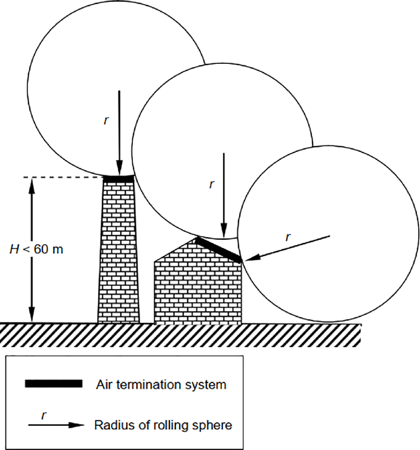
3.Rolling Sphere Method (RSM) LPS
The Rolling Sphere Method is a widely recognized method for calculating the area protected by a lightning protection system. It is often used to design conventional LPS but can also apply to advanced systems like ESE LPS.
Key Components of Conventional RSM
-
Lightning Rods
Placed according to a design calculated with the rolling sphere model.
-
Down Conductors and Grounding System
To channel and dissipate the lightning strike safely.
Working Principle
In this method, a virtual sphere is rolled over the building at a defined radius. The lightning protection system is designed to cover the entire structure within the sphere’s reach, ensuring all vulnerable areas are protected.
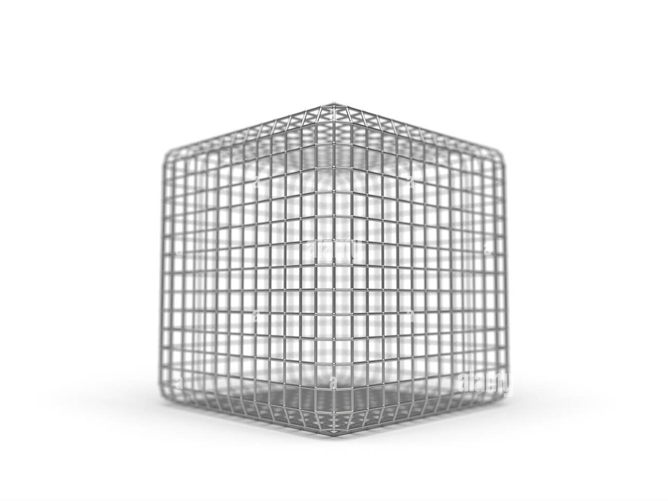
4.Faraday Cage (Mesh System) LPS
A Faraday Cage is a type of LPS used for protecting large structures like industrial plants, communication towers, and historical buildings. It involves installing a mesh of conductors around the building or structure to create a protective barrier.
Key Components
-
Conductive Mesh
A metal mesh or grid placed around the structure.
-
Earthing System
Ground electrodes connected to the mesh to safely dissipate the electrical charge.
Working Principle
The Faraday Cage works by directing the lightning strike to the mesh, which then conducts the electrical energy into the ground. This system is effective for large structures or those with sensitive equipment that need comprehensive protection.
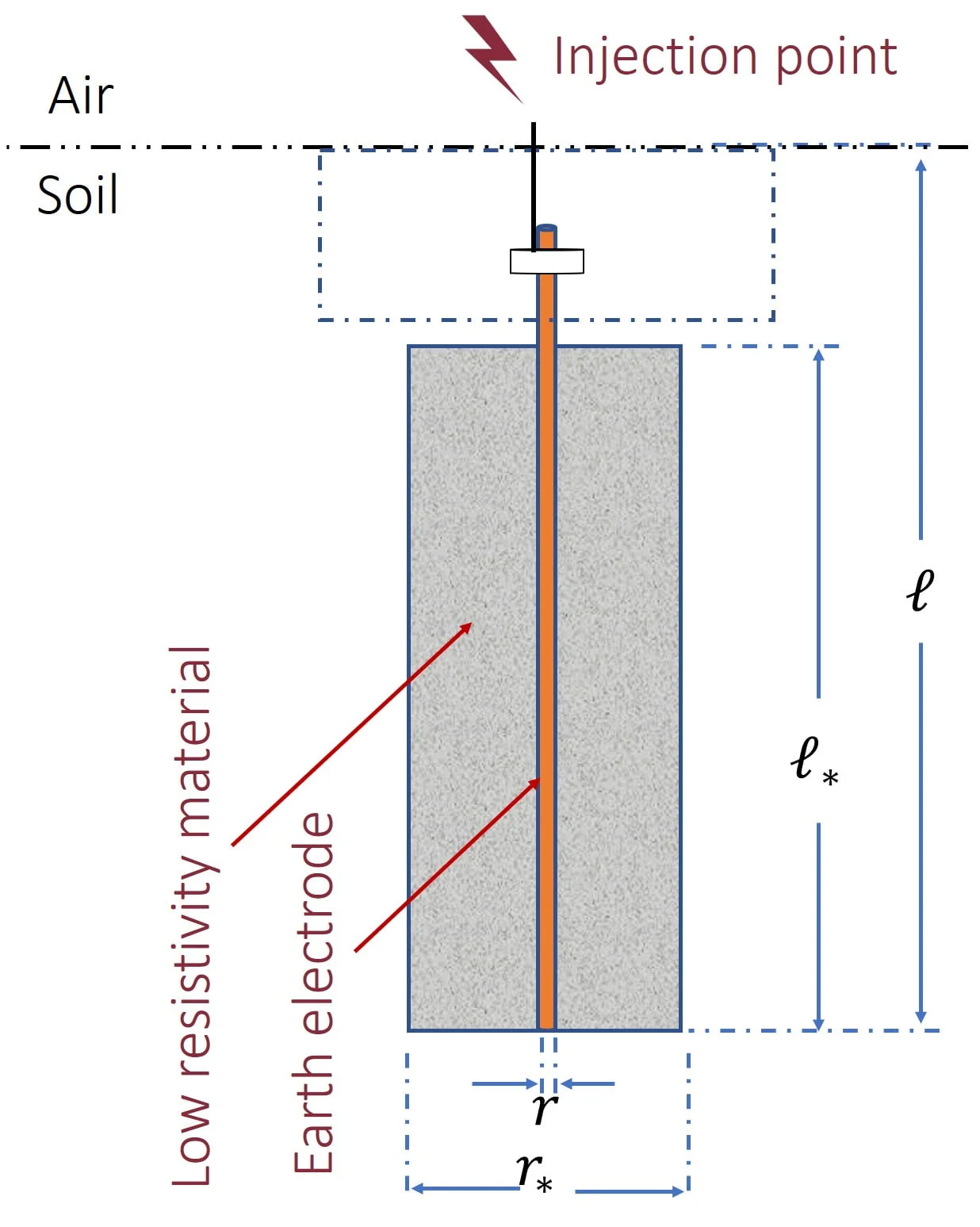
5.Chemical Earthing LPS
This system enhances the effectiveness of the grounding system in an LPS by using chemical electrodes to reduce the ground resistance and improve the dissipation of electrical charges.
Key Components
-
Chemical Electrodes
Electrodes treated with conductive chemicals that lower ground resistance.
-
Earthing System
This system is integrated with the overall LPS to ensure proper grounding.
Working Principle
The chemical electrodes help in reducing the resistance of the ground, which improves the efficiency of the lightning protection system, particularly in areas with poor soil conductivity.
6.Integrated (Hybrid) LPS
An Integrated LPS combines multiple types of protection systems to offer enhanced safety. It may include a combination of conventional lightning rods, ESE air terminals, and Faraday Cage systems, depending on the needs of the building or structure.
Key Components
-
Combination of Systems
It integrates components from traditional LPS, ESE systems, and grounding systems.
-
Customized Design
The system is designed to suit specific needs, like large, complex buildings or high-risk areas.
Working Principle
This hybrid system ensures that different protection methods work together to provide comprehensive protection from lightning strikes. It is particularly useful for large or high-value structures that need extensive protection.
7.Surface or External LPS
This system focuses on protecting the external parts of a building or structure, such as roofs, walls, and external wiring. It includes lightning rods, conductors, and grounding systems.
Key Components
-
Air Terminals (Lightning Rods)
Installed at high points.
-
Down Conductors
Carry the lightning energy from the rods.
-
Grounding System
Directs the energy into the ground.
Working Principle
It is designed to protect the outer parts of the building from direct lightning strikes, channelling the energy safely into the ground. It’s often used in conjunction with internal protection systems.
The choice of Lightning Protection System (LPS) depends on the structure’s size, location and level of protection needed. Whether using a traditional system or an advanced ESE system, the goal is the same: to protect people, equipment, and structures from the devastating effects of lightning. The combination of various methods can offer the best protection for large or critical facilities.
LPS Design Methods
Acceptable methods for designing the lightning protection system as per IS IEC 62305
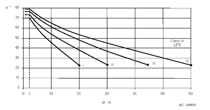
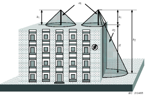
Protection Angle method
suitable for simple structures or for small parts of bigger structures. This method is not suitable for the structures higher than the radius of the rolling sphere relevant to the selected protection level of the LPS.
Air-termination rods should be positioned so that all the parts of the structure to be protected are inside the envelope surface generated by projected points on the air-termination rods to the reference plane. The protection angle should confirm to the table mentioned below, with h being the height of the air-termination above the surface to be protected.
-
Note 1:
The protection angle method has geometrical limits and cannot be applied if H is larger than the rolling sphere radius, r.
-
Note 2:
The angle will not change for values of H below 2 m
-
Note 3:
H is the height of the air-termination above the reference plane of the area to be protected.
H : Height of the building over the ground reference plane
h1 : Physical Height of an air termination rod
h2 : h1 + H, being the height of the air termination rod over the ground
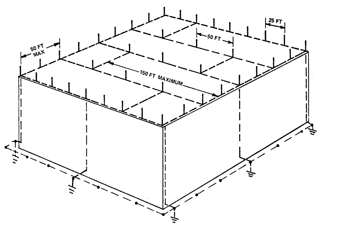
Mesh Method
Suitable for the protection of plane surfaces. The choice of the method depends on a practical evaluation of its suitability and the vulnerability of the structure to be protected.
Mesh method is considered to protect the whole surface if the following conditions are fulfilled
a) Air-termination conductors are positioned on –
-
Roof edge lines
-
Roof overhangs
-
Roof edge lines, if the roof slope exceeds 1/10,
-
The lateral surfaces of the structures of the structure higher than 60 Mts at levels higher than 80 % of the height of the structure
b) The mesh dimensions of the air termination network are not greater than the values mentioned in the below mentioned table.
| Class of LPS | Protection Method | |
|---|---|---|
| Rolling Sphere Radius ‘r’ Mtr |
Mesh Size ‘W’ Mtr |
|
| I | 20 | 5 x 5 |
| II | 30 | 10 x 10 |
| III | 45 | 15 x 15 |
| IV | 60 | 20 x 20 |
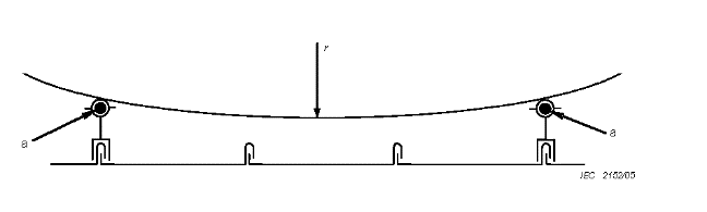
Rolling sphere method
suitable for complex shaped structures.
Applying this method, the positioning of the air-termination system is adequate if no point of the volume to be protected is in contact with a sphere of radius r, rolling on the ground and on top of the structure in all possible directions. Therefore, the sphere should touch the ground and / or the air-termination system.
The radius r of the rolling sphere depends on the class of LPS. In case there are two parallel horizontal LPS air-termination conductors placed above the horizontal reference plane, the penetration distance ‘p’ of the rolling sphere below the level of the conductors in the space between the conductors may be calculated :
P = r – r² – (d/2)²
Note : The penetration distance ‘p’ should be less than the physical height of the air-termination rods above the reference plane minus the height of the objects to be protected.
| Protection Method | Simple Structures | Complex Shaped Structures | Plane Structures |
|---|---|---|---|
| Protection angle | ✓ | X | X |
| Mesh method | X | X | ✓ |
| Rolling sphere method | ✓ | ✓ | ✓ |
| Note: The Protection angle method is not suitable for structures higher than the radius of the rolling sphere relevant to the selected protection level of the LPS. | |||